

In This Guide
1. Factors Affecting Plating Rectifier Performance
2. Pre-Start Checks for Your Plating Rectifier
3. Voltage Drift on the Plating Rectifier with Fixed Current
4. Can One Plating Rectifier Serve Multiple Tanks?
5. Plating Rectifier Specification: Information to Provide
6. Plating Rectifier Electrical Data Alone Is Insufficient
7. Daily Operating Habits for Plating Rectifier Reliability
8. Conclusion

Your rectifier display shows a steady current. That does not mean your parts are plating evenly—and that single misunderstanding causes more scrap than you might think.
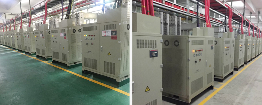
Plating rectifiers convert AC power into adjustable DC output, providing stable current and voltage for electroplating. But proper plating rectifier operation goes far beyond setting a number and pressing start. Operators must consider multiple interdependent factors: workpiece surface area, rack and fixture contact condition, bath resistance, target current density, ramp time, and the plating rectifier’s allowable voltage range.
This article focuses on practical plating rectifier operation—what readings actually matter, what to check before and during the plating cycle, and how to use electrical data from the plating rectifier to diagnose coating quality issues.
Factors Affecting Plating Rectifier Performance
The plating rectifier does not operate in isolation. It responds dynamically to changes inside the plating tank. The operator sets a target, but the plating rectifier’s actual output is influenced by:
• Total surface area in the bath—loading changes directly affect total current the plating rectifier must deliver
• Rack and contact condition—poor contacts add resistance and cause uneven current distribution from the plating rectifier
• Bath resistance—varies with temperature and chemical composition, affecting the plating rectifier’s voltage requirement
• Ramp profile settings—soft start helps avoid shock plating when parts enter the bath
• Plating rectifier voltage limit—output cannot maintain set current once this limit is reached
• All of these factors interact. Change any one, and the plating rectifier’s output changes accordingly. Understanding this dynamic relationship is fundamental to proper plating rectifier operation.
Pre-Start Checks for Your Plating Rectifier
The following checks are required before every plating cycle:
1. Compare set current against actual current on the plating rectifier
After the load connects, verify the plating rectifier’s displayed current matches the set value. A deviation within 2% is normal. Beyond that, stop and investigate.
Key takeaway: Always compare set current against actual current on the plating rectifier after the load connects. A deviation beyond 2% requires investigation—do not assume the plating rectifier is functioning correctly.
2. Inspect electrical connections to the plating rectifier
Check hooks, racks, barrels, busbars, and cable joints from the plating rectifier to the tank. Visually examine all connections. If safe, touch for abnormal heat. Hot spots indicate poor contacts—they add resistance, waste power, and create uneven current distribution from the plating rectifier that directly affects plating quality.
3. Verify plating rectifier cooling system operation
Check fans running, coolant circulating, and no overtemperature alarms active on the plating rectifier. Heat damages plating rectifiers and can cause output drift when the unit derates. Some heavy-duty plating rectifiers use closed-loop water cooling for continuous high-current operation.
4. Document and correlate observations with plating rectifier readings
Link plating rectifier electrical readings to actual defect records. Pitting? Burning? Thin coverage? Look at the bath and pretreatment before you blame the plating rectifier. Nine times out of ten, it is the chemistry, the filter, or the cleaning step—not the plating rectifier.
Voltage Drift on the Plating Rectifier with Fixed Current—What Is Going On?
This phenomenon on the plating rectifier often confuses operators.
Example: Plating rectifier current set at 500 A, voltage reads 8 V. Ten minutes later, the plating rectifier shows 8.5 V. The current setting on the plating rectifier never changed. What happened?
Some parameter in the circuit shifted:
• Load surface area increased
• Contact oxidation developed
• Bath temperature changed
• Anode-to-cathode spacing shifted due to rack movement
The plating rectifier adjusts voltage to maintain set current—that is its primary function. If the plating rectifier’s voltage hits the maximum and current still falls short, a process limitation exists. Minor voltage fluctuations on the plating rectifier are normal responses to changing circuit resistance. Learn to read these variations on your plating rectifier rather than treating them as faults.
Can One Plating Rectifier Serve Multiple Tanks?
Possible, but requires careful evaluation.
Key questions about using a single plating rectifier for multiple tanks:
• Can each tank be electrically isolated, or is a single busbar feeding everything from one plating rectifier?
• Do the tanks run the same recipe or different ones, requiring different plating rectifier outputs?
• What is the combined maximum demand on the plating rectifier?
• Are interlocks in place to prevent overloading the plating rectifier?
• Does cooling have adequate capacity for the plating rectifier under full load?
A problem in one tank pulls down everything connected to the same plating rectifier. A few newer plating rectifiers are built with parallel modules and N+1 backup. One module can drop out for service while the rest keep running. That gives you a lot more flexibility than a single big plating rectifier.
Here is the trade-off: pay more now for separate plating rectifiers or modular gear, or pay later with overtime hours spent tracking down problems that jump between tanks fed by one plating rectifier.
Plating Rectifier Specification: Information to Provide
Do not call a supplier and say “give me a 1000 amp plating rectifier.” They will need much more. Provide the full plating rectifier specification upfront to save everyone time.
Essential parameters for specifying a plating rectifier:
• Process type—nickel, copper, chrome, anodizing, pulse plating? This determines the plating rectifier’s output characteristics
• Maximum part surface area per load—directly affects plating rectifier current rating
• Current density range—minimum and maximum required, defining the plating rectifier’s operating window
• Calculated current and voltage requirements—the plating rectifier must meet both
• Duty cycle—continuous or intermittent, affecting plating rectifier cooling needs
• Input power—voltage, phase, frequency available to the plating rectifier
• Cooling method available—air, water, ambient temperature for the plating rectifier
• Control interface—analog, digital, PLC, remote panel for the plating rectifier
• Installation space—footprint, mounting style for the plating rectifier
A good supplier will extract all this eventually. Provide it on the first call and get a real quotation for your plating rectifier—not a guessing game.

Plating Rectifier Electrical Data Alone Is Insufficient
Plating rectifier readings help—but they only show part of the picture.
To properly diagnose, cross-reference plating rectifier data with:
• Bath chemistry—metal content, additives, pH levels
• Temperature logs—bath and ambient temperature records
• Filter pressure—clogged filters alter flow and current distribution from the plating rectifier
• Pretreatment quality—cleaning, activation, rinsing effectiveness
• Part geometry—flat panels behave differently from complex shapes, affecting what the plating rectifier must deliver
Diagnostic Guidelines for Plating Rectifier Issues
| Observation on Plating Rectifier | Likely Cause | Action |
| Voltage high, current normal on plating rectifier | Poor conductivity | Check anodes, contacts, bath conductivity |
| Voltage normal, poor recess coverage | Throwing power issue | Check bath additives and dispersion—not the plating rectifier |
| Sudden voltage spike on plating rectifier | Open circuit | Check broken contact or loose cable to plating rectifier |
| Current hunting or oscillation on plating rectifier | Control loop problem | Check tuning and feedback signal quality to plating rectifier |
| Overtemperature alarm on plating rectifier | Cooling failure | Inspect fan, airflow, filter blockage on plating rectifier |
Key takeaway: Always match symptoms to the entire system—not just the plating rectifier. Most faults trace to chemistry, filtration, or cleaning, not the plating rectifier.
Daily Operating Habits for Plating Rectifier Reliability
Take readings from the plating rectifier consistently
Record plating rectifier voltage and current at three points each cycle—start, middle, finish. Single readings from the plating rectifier provide little insight. Trends in plating rectifier data reveal what is actually happening.
Keep spare parts for the plating rectifier
Stock spare fuses, cooling fans, and contactors for your plating rectifier. Components cost relatively little. Plating rectifier downtime costs significantly more.
Perform regular maintenance on the plating rectifier
Clean busbar connections to the plating rectifier on schedule. Even a thin oxide layer introduces measurable resistance that affects plating rectifier efficiency.
Train operators on plating rectifier operation
Teach operators to recognize abnormal sounds and smells from the plating rectifier, not just display readings. A transformer hums during normal operation—buzzing on the plating rectifier indicates trouble.
Investigate before resetting the plating rectifier
Never reset a plating rectifier alarm and restart without identifying the root cause. Plating rectifier alarms exist for good reasons.
Conclusion
Plating rectifiers are generally reliable equipment that perform as specified. The most common sources of plating problems lie elsewhere—in contacts, bath chemistry, cooling systems, and operator monitoring of the plating rectifier.
Effective plating rectifier control requires attention to the complete system, thorough data recording from the plating rectifier, and response to trends in plating rectifier readings rather than isolated faults. The plating rectifier is a tool to be understood and utilized properly—not a frequent source of problems.
Among them, our electroplating rectifiers are extensively utilized for PCB electroplating, hard chrome coating, copper/nickel/zinc plating, and precious metal plating with gold and silver — delivering reliable power solutions for diverse hardware surface treatment applications.