
AC comes in from the grid. Three phases. 380V or 480V — depends on where you are and what your facility’s step-down transformer delivers. The electroplating rectifier sits between that incoming power and the plating tank. Its job: convert AC into DC that the bath can use.
The DC output needs to be at a voltage that matches the plating bath’s requirements. That’s usually low, but the exact number depends on the chemistry. Current can be modest for a small manual line or substantial for continuous strip plating. Those are just nameplate numbers, though. The real issue is what the DC looks like after it leaves the plating rectifier terminals.
The Basic Architecture
Most rectifiers share a common layout. A transformer handles the voltage adjustment. A rectifier stage does the AC-to-DC conversion. A filter section smooths the output. A control circuit keeps things stable. The technology used in each of these sections has evolved over time, but the overall arrangement hasn’t changed much.
Transformers
In a line-frequency rectifier, the transformer runs at 50 or 60 Hz. The core is laminated steel. The windings are copper. That combination is heavy and the losses add up — hysteresis in the steel, eddy currents in the laminations, copper resistance in the windings. Heat is a constant problem.
High-frequency designs are different. The transformer runs at 20 kHz or more. The core is ferrite. The whole thing is small — a fraction of the size and weight. But there’s a catch: you can’t just feed 50 Hz AC into a ferrite transformer. You have to convert the incoming AC to DC first, then switch that DC at high frequency to create a new AC waveform, then feed that to the transformer. On the secondary side, you rectify it again.
It sounds like extra work, and it is. But the gain in size reduction and efficiency makes it worthwhile for most installations. For anyone specifying an electroplating rectifier, this trade-off is worth understanding.
How the Conversion Happens
In an SCR plating rectifier, the thyristors fire at controlled points in each AC cycle. A firing angle of zero degrees gives maximum output. A firing angle near the end of the half-cycle gives almost nothing. Between those extremes, the output is adjustable.
The DC that comes out isn’t smooth. It’s a series of humps. A three-phase, six-pulse bridge produces six of those humps per AC cycle. The count is 300 per second if you’re on a 50 Hz supply, and 360 if you’re on 60 Hz.
Each hump deviates from the average DC level. That deviation is the ripple. The magnitude of the ripple changes with load and firing angle — generally worse at mid-range outputs.
High-frequency units take a different path. The front-end rectification is usually done with diodes — a straightforward bridge that produces a rough DC. Then the IGBTs or MOSFETs switch that DC on and off at high frequency, creating a pulsed waveform that goes through the transformer. The secondary is rectified again.
In these units, the ripple frequency follows the switching frequency — tens of kilohertz, not a few hundred hertz. That shift changes the filtering requirement considerably. It’s one reason modern electroplating rectifier designs can achieve better output quality with smaller components.
Filtering
Ripple is undesirable because the plating process responds to instantaneous current. If the current cycles up and down, the cathode potential cycles with it. That affects how metal ions deposit.
The filter section exists to reduce that cycling. Inductors resist changes in current flow, so they tend to hold the current steady through the peaks. Capacitors do the opposite — they store energy when the voltage is high and release it when the voltage drops. Together, they smooth the waveform.
There are trade-offs. Inductors are wound with wire that has resistance. That resistance represents a loss — energy turned into heat. Capacitors age; their internal resistance increases and their performance declines. More filtering means lower ripple but also lower efficiency and higher cost. That’s why a low ripple DC power supply for electroplating isn’t just a matter of adding more components — it’s a careful balance.
With SCR rectifiers, the choke is large and it dissipates a fair amount of heat. With high-frequency rectifiers, because the ripple frequency is so much higher, the choke can be smaller and still effective. That’s one reason high-frequency designs tend to deliver both lower ripple and better overall efficiency. If you’re evaluating a plating rectifier for a new line, this is a key differentiator.
Regulation
The control loop monitors the output and adjusts the rectifier to maintain the setpoint. In constant-current mode — the typical choice for plating — the controller reads the output current, compares it to the target, and changes the firing angle or pulse width accordingly.
The loop runs continuously. In an SCR unit, the update rate is limited by the line frequency — one adjustment per half-cycle. In a high-frequency unit, the loop can update every switching cycle. The difference in response speed is two orders of magnitude.
That speed becomes important during load changes. When a rack of parts enters the tank, the resistance of the bath changes almost instantly. A slow regulator lets the current dip before correcting. A fast regulator catches the dip quickly and brings it back.
The dip might last only a few milliseconds. But during that brief window, the parts at the leading edge of the rack see a different current density than the parts at the trailing edge. That translates into thickness variation across the rack. For production lines where PCB plating requires tight tolerances, this response characteristic of the electroplating rectifier — its ability to maintain constant current plating power supply stability — matters a great deal.
What Matters in the Output
The DC that reaches the plating tank has several characteristics worth tracking.
The average current and voltage are the operator’s setpoints. They determine the deposition rate. They also influence grain structure, though the relationship isn’t linear.
The ripple amplitude is the deviation from the average. Applications vary in their tolerance. General industrial plating can handle a few percent. Hard chrome, precious metals, and semiconductor work are less forgiving.
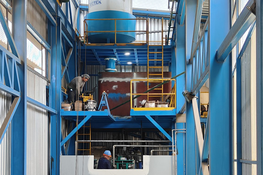
Hard Chrome Plating Rectifier Project in Peru
The rectifier ripple specification you’ll see on a datasheet usually quotes a percentage — but always ask at what load and under what conditions that number was measured.
Ripple frequency matters too, though it doesn’t get as much attention. The electrode surface has a double-layer capacitance. That capacitance charges and discharges with the ripple. At low ripple frequencies — a few hundred hertz — the double layer has time to discharge between cycles. The effective potential follows the instantaneous current. At high ripple frequencies — tens of kilohertz — the double layer doesn’t fully discharge, so the effective potential stays closer to the average.
This is a subtle effect, but it explains why a high-frequency plating rectifier with the same measured ripple percentage as an SCR unit can still produce a denser, finer deposit.

How Rectifier Performance Affects Plating Quality
The connections between rectifier output and deposit properties are well documented.
Start with grain structure. Higher current density promotes nucleation — more new crystallites forming on the surface. But that’s only true if the current is steady. When the current varies, nucleation doesn’t happen uniformly across each cycle. Some grains get a head start and grow faster; the resulting structure is columnar rather than equiaxed. Columnar grains don’t handle stress or corrosion as well.
Porosity is another connection. Ripple creates periodic variations in overpotential. During parts of each cycle, the deposition becomes mass-transport-limited in certain micro-regions, leading to gaps in the coating. Those gaps become initiation points for corrosion.
Adhesion depends on the first few seconds of deposition. If the current fluctuates during that initial period, the nucleation layer is patchy. A patchy interface means the coating hasn’t bonded uniformly to the substrate.
Organic additives are also affected. Levelers, brighteners, and stress reducers adsorb onto the cathode at rates that depend on the surface potential. If the potential oscillates, adsorption isn’t uniform across the part. The result is streaky finishes or inconsistent brightness.
Each of these effects is observable and measurable. They connect back to electroplating rectifier performance through the same parameters: ripple, regulation accuracy, and response time.
High-Frequency and Synchronous Rectification
SCR plating rectifiers are still around, especially in older facilities and very high-power applications where initial cost is the overriding factor. But for new installations, high-frequency switching has become the default.
The reasons are practical. Efficiency is better. Regulation is faster. The physical footprint is smaller. Those three factors translate directly into operating cost, reject rates, and floor space.
Synchronous rectification represents the latest refinement. In a conventional secondary rectifier, diodes handle the final conversion. Diodes have a forward voltage drop — a fixed loss that occurs any time current flows. In a synchronous design, MOSFETs replace the diodes. When turned on, a MOSFET behaves like a low-value resistor. The conduction loss is lower, especially at high current.
This is not a new idea. Synchronous rectification has been used in low-voltage power supplies for years. But the cost of MOSFETs has come down, and their performance has improved, so the approach has become practical for industrial rectifiers. Leading equipment suppliers — including those serving the electrolytic copper foil and PCB sectors — have adopted this technology across their product lines. Liyuan Haina Rectifier, for instance, has implemented it across their third-generation products. The company holds the dominant market position in China’s electrolytic copper foil power supply segment, a sector where current stability and efficiency are non-negotiable.
The benefit is straightforward: less heat, smaller cooling systems, longer component life. The underlying sequence — transformer, rectifier, filter, regulator — stays the same. For anyone looking at a new electroplating rectifier, or considering an upgrade, this is worth a close look.
What to Ask When Buying
If you’re specifying a plating rectifier, start with the basics. Voltage and current must match your bath and your production volume. Oversizing means running inefficiently at light load. Undersizing limits throughput and may stress the unit.
Ripple is worth verifying. Ask for the rectifier ripple specification at your typical operating point, not just at full load or at a single test condition. Understand how it changes across the load range.
Regulation accuracy is another spec to confirm. ±1% is typical. Some processes need tighter. Ask about transient response too — how the unit behaves during load steps.
Cooling depends on your facility. Air-cooled units are simpler. If your shop is dusty, hot, or chemically aggressive, water-cooled may be the better choice.
Control interface matters for integration. RS485 is common. Some plants use Ethernet or analog signals. Match what you already have.
Finally, look at the supplier’s history in your specific application. A rectifier for electroplating that runs well in one industry may not be optimized for another. Suppliers with proven track records in demanding sectors — high-precision PCB, copper foil, semiconductor plating — tend to have deeper application engineering expertise.
The rectifier tends to get forgotten until something goes wrong. It runs quietly, usually without attention, and the parts keep coming off the line. But the quality of those parts depends directly on the quality of the DC it delivers. Once you understand the internal stages — transformer, rectifier, filter, regulator — the electroplating rectifier is no longer a black box. You can specify it with confidence, diagnose issues when they come up, and match it to your process with far more precision.
Among them, our electroplating rectifiers are extensively utilized for PCB electroplating, hard chrome coating, copper/nickel/zinc plating, and precious metal plating with gold and silver — delivering reliable power solutions for diverse hardware surface treatment applications.